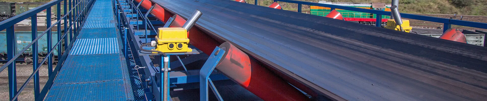
Load-bearing idler sets, also known as troughing idlers, are the primary, structural backbone of any belt conveyor system. Positioned along the conveyor's carrying side, they are responsible for supporting the total weight of both the conveyor belt and the bulk material load, shaping the belt into a trough for greater capacity and stable transport. Their performance is directly linked to the system's efficiency, energy consumption, and operational longevity.
Core Function & Design:
Unlike single return idlers, load-bearing idlers are configured in sets—most commonly 3-roll or 5-roll designs—to create a trough shape. The center roll provides base support, while the inclined wing rolls (at angles of 20°, 35°, or 45°) contain the material and increase cross-sectional load capacity. This design is critical for preventing spillage and maximizing throughput in industries like mining, aggregate, and agriculture.
Key Features & Benefits
| Feature |
Benefit |
| Optimized Trough Design |
20°, 35°, or 45° angles maximize material capacity while minimizing spillage |
| Heavy-Duty Steel Frame |
Rigid construction maintains roller alignment under full load |
| Precision-Sealed Bearings |
Labyrinth + contact seals prevent dust and moisture ingress |
| Low Rolling Resistance |
Reduces drive motor power requirements and energy costs |
| Smooth Belt Contact |
Precision-ground tube surface minimizes belt abrasion |
| Interchangeable Design |
CEMA / DIN standard dimensions fit existing conveyor structures |
| Corrosion Protection |
Hot-dip galvanized, painted, or stainless steel options |
| Long Service Life |
30,000 – 50,000 hours under normal operating conditions |
Available Configurations
| Configuration |
Trough Angle |
Description |
Application |
| 20° Troughing Idler |
20° |
Shallow trough; gentle material containment |
Light materials, low belt speeds, fragile products |
| 35° Troughing Idler |
35° |
Standard industry angle; best balance of capacity and belt life |
Most general bulk material handling |
| 45° Troughing Idler |
45° |
Deep trough; maximum material capacity |
High-tonnage conveyors, steep inclines |
| Variable Trough Idler |
Adjustable |
Wing rollers can be repositioned to different angles |
Test conveyors, custom applications |
| Flat Load-Bearing Idler |
0° (flat) |
Single horizontal roller |
Flat belt conveyors, light-duty applications |
Technical Specifications
| Parameter |
Standard Range |
| Belt Width |
400 mm – 2400 mm (16" – 96") |
| Trough Angle |
20°, 35°, or 45° (custom angles available) |
| Roller Diameter |
89 mm, 108 mm, 133 mm, 159 mm, 194 mm (3.5" – 7.6") |
| Roller Wall Thickness |
2.5 mm – 5.0 mm (depending on diameter and load) |
| Shaft Diameter |
20 mm – 40 mm (cold-drawn round steel, Grade 45# / C45) |
| Bearing Type |
Deep groove ball bearing (6204, 6205, 6206, 6305, 6306, 6307, 6308) |
| Bearing Clearance |
C3 (standard) for temperature variation |
| Sealing System |
Double labyrinth seal + rubber flinger (dustproof / waterproof) |
| Grease |
Lithium-based grease (NLGI #2) |
| Frame Material |
Heavy-duty steel channel (C-channel or box section) |
| Frame Thickness |
4 mm – 8 mm (depending on load rating) |
| Mounting |
Base plate or channel mount (bolted to conveyor stringer) |
| Temperature Range |
-30°C to +60°C (-22°F to 140°F) |
Component Breakdown
| Component |
Material / Specification |
Function |
| Center Roller |
Steel tube, 20° – 45° horizontal orientation |
Supports belt center and majority of material load |
| Left Wing Roller |
Steel tube, angled upward (left side) |
Forms left side of trough; contains material |
| Right Wing Roller |
Steel tube, angled upward (right side) |
Forms right side of trough; contains material |
| Center Bracket |
Fabricated steel plate |
Holds center roller; connects to side frames |
| Side Frames |
Steel channel or formed plate |
Mount wing rollers; attach to center bracket |
| Pivot Base (if adjustable) |
Steel plate with pivot pin |
Allows frame to pivot for belt tracking (self-aligning models) |
| Mounting Feet |
Steel plate with bolt holes |
Secures idler set to conveyor stringer |
| Roller Tube |
ERW carbon steel (Q235B or higher) |
Direct belt contact surface |
| Shaft |
Cold-drawn round steel (Grade 45# / C45) |
Supports roller; transfers load to frame |
| Bearing |
Deep groove ball bearing, C3 clearance |
Enables smooth, low-friction rotation |
| Bearing Housing |
Steel casting or precision insert |
Holds bearing; pressed into tube ends |
| Labyrinth Seal |
Steel or plastic rings |
Prevents dust ingress via tortuous path |
| Flinger Seal |
Rubber |
Throws out contaminants; retains grease |
| End Cap |
Steel or plastic |
Protects seal from external damage |
Trough Angle Comparison
| Trough Angle |
Material Capacity |
Belt Stress |
Best Application |
| 20° |
Low |
Lowest |
Fragile materials, low belt speeds, flat conveyors |
| 35° |
Medium |
Moderate |
General purpose; most common angle |
| 45° |
High |
Higher |
High-tonnage, steep inclines, non-abrasive materials |
Note: Higher trough angles increase material capacity but also increase belt edge stress. For abrasive materials, a 35° trough is typically recommended.
Load-Bearing vs. Other Idler Types
| Feature |
Load-Bearing Idler |
Impact Idler |
Return Idler |
| Location |
Carrying side (full conveyor length) |
Loading zones only |
Return side |
| Roller Type |
Solid steel tube |
Rubber disc or sleeve |
Flat or V-return |
| Impact Resistance |
Standard (not for high drop heights) |
High (rubber cushioning) |
N/A |
| Self-Cleaning |
No |
Yes (open disc spacing) |
V-return or disc types |
| Primary Function |
Support material load |
Absorb impact energy |
Support empty belt |
| Trough Angle |
20°, 35°, 45° |
20°, 35°, 45° |
0° (flat) or 10° (V) |
Applications
| Industry |
Typical Use |
| Mining |
Overland conveyors, underground belt systems, incline conveyors |
| Aggregates & Quarrying |
Crushing/screening plant conveyors, stockpile feed belts |
| Cement |
Raw material feed, clinker conveyors, finished product belts |
| Power Generation |
Coal handling conveyors, ash handling systems |
| Port & Terminal |
Ship loading/unloading, yard conveyors, stacker/reclaimer belts |
| Bulk Material Handling |
Grain, fertilizer, salt, sand, gravel, wood chips, biomass |
| Steel & Smelting |
Ore conveyors, sinter feed, scrap handling |
| Food Processing |
Light-duty stainless steel versions (wash-down capable) |
Recommended Idler Spacing
| Belt Width |
Material Density (light) |
Material Density (medium) |
Material Density (heavy) |
| < 800 mm (32") |
1.5 m (5 ft) |
1.2 m (4 ft) |
1.0 m (3.3 ft) |
| 800 – 1200 mm (32-48") |
1.5 m (5 ft) |
1.2 m (4 ft) |
1.0 m (3.3 ft) |
| 1200 – 1600 mm (48-63") |
1.2 m (4 ft) |
1.0 m (3.3 ft) |
0.8 m (2.6 ft) |
| > 1600 mm (63") |
1.2 m (4 ft) |
1.0 m (3.3 ft) |
0.8 m (2.6 ft) |
Loading Zone: Reduce spacing to 0.6–0.8 m (2–2.6 ft) at loading zones and transfer points.
Selection Checklist
When ordering load-bearing idler sets, please specify:
Belt width (mm or inches)
Trough angle (20°, 35°, or 45°)
Roller diameter (based on belt speed and load)
Roller wall thickness (standard or heavy-duty)
Material type & density (kg/m³ or lbs/ft³)
Expected tonnage (tons per hour)
Belt speed (m/s or fpm)
Idler spacing (center-to-center distance)
Frame finish (painted, hot-dip galvanized, or stainless steel)
Sealing requirement (standard dustproof or heavy-duty waterproof)
Accessories (mounting bolts, retaining clips, side guide rollers)
Quality Standards
All load-bearing idler sets are manufactured to:
ISO 9001:2015 – Quality management system
CEMA B105.1 – Idler dimensions and load ratings
DIN 15207 / ISO 15360 – Roller specifications
JIS B 8803 (available upon request)
SANS 1313 (mining applications)
Each set undergoes 100% inspection for:
Roller radial runout (≤0.5 mm)
Rotational resistance (≤3.0 N per roller)
Axial displacement (≤0.5 mm)
Bearing smoothness (audible/rotation test)
Frame alignment and squareness
Paint thickness / galvanizing verification
*Load-bearing idler set, carrying idler, troughing idler set, conveyor support roller, weight-bearing idler, 35 degree troughing idler, heavy-duty carrying idler, belt conveyor idler set, CEMA idler set, troughing roller assembly, material support roller, conveyor load roller, steel troughing idler, bulk handling idler, mining conveyor idler.*