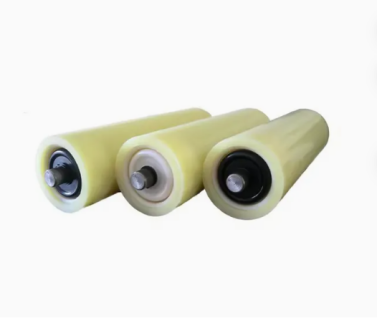
Rubber conveyor rollers and idlers are critical components of belt conveyor systems designed to improve belt tracking, enhance driving friction, absorb severe dynamic impacts, and protect heavy-duty belting from abrasion, material buildup, and misalignment in demanding bulk handling environments. Unlike standard plain steel variants, rubber-covered or rubber-disc idlers deliver enhanced structural protection for the conveyor belt, drastically reduce ambient operating noise, and sustain optimal performance under continuous, heavy-load, or corrosive operating conditions.
At a Glance
Section
Summary
What Are Rubber Conveyor Rollers?
An introductory technical overview explaining rubber conveyor rollers, their core mechanical function, elastomer formulations, and primary role in mitigating belt slippage and structural wear across heavy-duty processing operations.
How Do Rubber Conveyor Rollers Work?
A comprehensive breakdown of the four distinct physical mechanisms governing rubber roller performance, including friction transfer, impact energy dampening, material shedding geometry, and tracking control.
Key Components of a Rubber Conveyor Roller System
A detailed structural analysis covering the central steel shaft, precision bearing assemblies, dynamic multi-lip labyrinth seals, robust steel core tubing, and specialized outer rubber vulcanized shell or elastomeric discs.
Benefits of Rubber Conveyor Rollers for Factory Operations
An in-depth evaluation of primary industrial operational advantages, focusing on extended belt service life, noise decibel reduction, total wear mitigation, and optimized energy transmission efficiency.
How to Choose the Right Rubber Conveyor Rollers for Your Factory
A strategic engineering selection roadmap outlining key parameters such as shore hardness ratings, thermal resilience, chemical exposure compatibility, belt speed specs, and load rating calculations.
What Are Rubber Conveyor Rollers?
Rubber conveyor rollers are precision engineered cylindrical components wrapped or sleeved in elastomeric compounds that provide superior traction, dynamic dampening, and belt tracking performance for bulk material conveying systems.
In heavy processing industries, conveyor reliability depends on maintaining structural harmony between moving belt covers and supporting mechanical components. Standard bare steel rollers are vulnerable to continuous friction loss, moisture-induced slippage, and aggressive material carryback buildup, which causes severe belt drift and edge degradation. To eliminate these operational vulnerabilities, industrial facilities rely on high-grade Rubber Conveyor Rollers and specialized rubber disc return idlers that alter the interface mechanics between the roller shell and bottom belt cover. Elastomeric shells present higher friction coefficients than polished metallic surfaces, ensuring reliable kinetic drive transfer even under wet, dusty, or oily operating environments. Furthermore, rubber formulations isolate structural vibrations, dampening peak load impacts at material transfer points before mechanical stresses reach internal bearing units.
From a materials engineering perspective, rubber conveyor rollers are manufactured using hot vulcanization or cold bonding techniques where premium Natural Rubber (NR), Styrene-Butadiene Rubber (SBR), Neoprene, or Nitrile (NBR) compounds are fused over high-tensile steel cores. European industrial clients frequently request high-durability elastomeric compounds engineered with shore hardness ratings tailored specifically to application demands, balancing high resilience against extreme cut and tear resistance. Incorporating custom rubber profiles into critical drive, impact, and return zones protects the structural integrity of expensive multi-ply fabric or steel-cord conveyor belts. By suppressing vibration harmonics and maintaining uniform rotational stability, these specialized components preserve system alignment, lower plant maintenance frequency, and extend continuous processing cycle times.
Technical Parameter
Standard Steel Idler
Rubber Covered / Disc Idler
Heavy Duty Vulcanized Impact Roller
Surface Friction Coefficient (Dry)
0.35 to 0.40
0.65 to 0.75
0.70 to 0.80
Surface Friction Coefficient (Wet)
0.10 to 0.15
0.35 to 0.45
0.40 to 0.50
Impact Energy Absorption
Very Low
Moderate to High
Exceptional
Noise Reduction Rating
Baseline (0 dB reduction)
5 dB to 8 dB reduction
8 dB to 12 dB reduction
Resistance to Material Carryback
Poor (Prone to shell scaling)
Excellent (Self-cleaning discs)
High (Elastomeric shedding)
Standard Shore Hardness
N/A (Solid Steel)
60 to 70 Shore A
50 to 60 Shore A
Rubber Roller Maintenance Considerations: Regular preventive inspections should monitor elastomer surface wear, checking for localized tears, chemical swelling, or grooving caused by trapped coarse particles. Ensure that oil contamination is minimized unless oil-resistant Nitrile rubber formulations are explicitly deployed within the system line.
How Do Rubber Conveyor Rollers Work?
Rubber conveyor rollers operate by increasing kinetic friction, absorbing kinetic drop energy through material elastic deformation, shedding sticky material carryback, and applying corrective lateral force vectors to maintain precise belt tracking alignment.
Understanding the precise mechanics behind rubber conveyor rollers requires evaluating four distinct operational mechanisms across the conveyor frame line. By strategically replacing rigid steel surfaces with elastomeric materials, plant managers can precisely control friction coefficients, load transfer forces, and belt drift behavior under continuous industrial operation.
Drive energy transmission within a belt conveyor system relies entirely on static and kinetic friction developed across the contact arc between the belt bottom cover and drive pulley lagging. Plain steel drive shells suffer from drastic friction drops in wet or humid atmospheres, leading to belt slippage, heat generation, and accelerated belt burning. Applying vulcanized rubber lagging with diamond or herringbone groove patterns dramatically raises the contact friction coefficient. As the conveyor belt wraps around the drive pulley, the elastomeric surface deforms slightly at a microscopic level, creating high mechanical traction and interlocking friction. Diamond and herringbone grooving channels channel surface moisture, slurry, and fine dust away from primary contact zones, preventing hydroplaning and maintaining full motor torque transfer under max load start-up conditions.
Step 2 — Deformation Energy Absorption (Impact Rollers)
When dense, sharp, or heavy bulk materials drop from feed chutes onto conveyor belts, the resulting kinetic shock forces generate extreme compressive stresses. Standard steel rollers offer zero elastic compliance, forcing the belt carcass to absorb the entirety of the falling impact energy, resulting in ply separation, longitudinal tearing, and premature structural failure. Heavy-duty rubber impact rollers feature a sequence of thick, resilient rubber rings or continuous elastomeric sleeves installed directly over the central steel core tube. Upon material impact, the rubber rings undergo controlled elastic deformation, absorbing dynamic shock forces and dampening peak impact energy before it reaches the precision internal bearings or structural conveyor frame.
Step 3 — Surface Geometry for Material Shedding
Material carryback, comprising wet fines and sticky mineral residue adhering to the return belt, poses a constant threat to conveyor alignment. When carryback contacts plain steel return rollers, sticky materials compact into uneven layers along the steel shell, altering the roller radius and causing continuous belt tracking errors. Rubber disc return idlers utilize specifically spaced elastomeric discs mounted along the steel tube, leaving open gaps between contact points. As the belt passes over these raised rubber discs, localized deflection and continuous flexural action shatter compacted material deposits, causing them to fall away harmlessly. The reduced contact surface area prevents sticky fines from accumulating, preserving constant roller concentricity and maintaining stable return path tracking.
Step 4 — Tensioner and Tracking Function (Wing Pulleys)
Corrective tracking and tensioning mechanisms require continuous lateral stability to prevent belt wandering toward structural side frames. Self-aligning tracking idlers mounted on swiveling guide frames utilize high-friction rubber roller sleeves to generate immediate directional correction vectors. When a conveyor belt drifts off-center, it places unequal gravitational force on one side of the tracking assembly. The increased friction between the rubber roller cover and the drifting belt activates the pivot mechanism, instantly steering the roller frame to guide the belt back into true center alignment. Utilizing highly durable heavy duty rubber conveyor rollers on tracking and tensioning assemblies ensures immediate response to belt wander, eliminating costly edge damage and spillages.
Operational Stage
Primary Physical Principle
Mechanical Component
Key Operational Benefit
Step 1: Drive Traction
Microscopic elastic traction and mechanical interlocking
Grooved Rubber Drive Lagging
Eliminates drive slippage and maximizes torque transfer efficiency
Step 2: Impact Dampening
Kinetic energy dissipation via elastic ring compression
Heavy Duty Rubber Impact Rollers
Prevents belt carcass puncture and extends bearing lifespan
Step 3: Material Shedding
Flexural deflection and localized contact disruption
Rubber Disc Return Idlers
Stops carryback accumulation and preserves true roller roundness
Step 4: Tracking Control
High-coefficient frictional vector correction
Rubber Covered Self-Aligning Rollers
Automatically corrects belt drift and prevents side edge damage
Working Principle Insight: European aggregate and mining plant operators overwhelmingly select diamond-grooved rubber lagging because the angled channels create high localized pressure zones that break fluid surface tension, delivering dependable drive grip during freezing winter operating conditions.
Key Components of a Rubber Conveyor Roller System
A professional rubber conveyor roller system comprises five primary structural components: a high-strength central steel shaft, precision anti-friction bearings, multi-stage labyrinth seals, a heavy-wall steel core shell, and a high-grade vulcanized rubber outer coating or disc array.
To withstand relentless radial loads, severe structural vibrations, and continuous wet or abrasive contamination, every structural element inside a rubber roller must be manufactured to stringent precision tolerances. Industrial engineering teams must understand how these internal components interact to ensure long service life and minimal maintenance downtime.
Central Precision Shafting
The central steel shaft carries the primary bending moments and shear stresses imposed by heavy material loads. Precision-machined from cold-drawn carbon steel or stainless steel alloys, the shaft features accurate lock-ring grooves and ground bearing seats to prevent micro-fretting corrosion during heavy continuous rotation.
Heavy-Wall Steel Core Shell
Beneath the outer rubber layer lies a heavy-wall seamless steel tube or high-grade ERW pipe that provides rigid structural support. The steel shell is precision-bored and trued to maintain low total indicator reading (TIR) runout, ensuring smooth rotational balance and preventing dynamic imbalance vibrations at high belt operating speeds.
Vulcanized Rubber Outer Coating or Disc Array
The outermost functional surface consists of high-grade elastomeric compounds fused directly to the steel shell via hot vulcanization or assembled as heavy-duty rubber rings under high axial compression. Natural rubber blends offer high elasticity and abrasion resistance, while Nitrile and Neoprene formulations deliver specialized oil, chemical, and flame-retardant properties.
Precision Anti-Friction Bearing Assemblies
Smooth rotation relies on deep groove ball bearings or spherical roller bearings designed with enlarged internal clearances (such as C3 or C4 specs). These precision bearings are positioned deep inside the housing end caps to deliver maximum load capacity and structural rigidity under extreme belt tensioning conditions.
Dynamic Multi-Stage Labyrinth Seals
The bearing cavity is protected by multi-lip labyrinth seals, outer dust caps, and contact lip seals that form a labyrinthine barrier against fine particulate dust, moisture, and chemical slurries. This complex seal arrangement keeps internal synthetic greases clean while keeping destructive external contaminants away from polished rolling elements.
Component Name
Material Specification
Primary Manufacturing Tolerance
Functional Purpose
Central Shaft
Carbon Steel C45 / Stainless Steel 304
h6 to g6 ground seat tolerances
Transmits load weight directly to support brackets
Steel Core Shell
Seamless Steel Pipe / Heavy ERW Tube
Runout TIR < 0.5 mm
Maintains cylindrical geometry and structural rigidity
Outer Rubber Surface
Natural Rubber / SBR / Nitrile / Polyurethane
50 to 70 Shore A (+/- 5)
Provides frictional grip, dampening, and abrasion protection
Bearing Assemblies
Deep Groove Ball (6204-6310) / Spherical
C3/C4 radial internal clearance
Ensures low-friction rotation under heavy radial forces
Labyrinth Seal Set
High-Density Polyethylene (HDPE) / Nylon
Multi-lip tight interference fit
Impenetrable barrier against water and microscopic dust
System Assembly Tips: When replacing worn rollers during plant overhauls, ensure shaft end slots fit tightly into bracket drop-in slots without angular twist. Misaligned support brackets cause uneven radial loading across internal roller bearings, leading to rapid seal failure and premature bearing seizure.
Benefits of Rubber Conveyor Rollers for Factory Operations
Implementing rubber conveyor rollers in factory operations delivers extended belt service life, significant noise reduction, reduced belt tracking errors, superior wear protection, and optimized system energy efficiency.
Modern industrial manufacturing facilities require continuous throughput with minimal unexpected machinery stoppages. Upgrading standard steel idlers to premium elastomeric variants provides tangible mechanical, environmental, and financial benefits across continuous processing lines.
Extended Conveyor Belt Service Life
Conveyor belting represents one of the highest capital expenditures in bulk material handling systems. Rubber conveyor rollers eliminate severe metal-to-belt wear, buffer high fall energy at feed chutes, and prevent abrasive wear caused by frozen or seized rollers, drastically extending expensive belt replacement intervals.
Noise Decibel Level Suppression
High noise levels generated by steel-on-steel impact and metal shell resonance present severe health and safety concerns in enclosed factory environments. Rubber roller sleeves damp metal vibrations and cushion structural contact, dropping ambient operating noise by up to 10 decibels to assist plant managers in achieving strict safety compliance.
Elimination of Belt Drift and Misalignment
By maintaining clean contact surfaces through self-cleaning rubber return discs and utilizing high-traction tracking rollers, rubber roller systems prevent disastrous belt drift. Eliminating off-center running stops material spillage along structural walkways and prevents catastrophic belt edge fraying against fixed conveyor framing.
Enhanced Energy Efficiency and Motor Protection
Continuous belt slippage over polished drive pulleys wastes electrical energy, increases motor heat, and imposes cyclic stress spikes on drive gearboxes. Applying rubber drive lagging and high-traction rubber return rollers ensures efficient torque conversion, maintaining consistent material transport speed while reducing power consumption.
Superior Resistance to Abrasive and Corrosive Wear
In facilities handling damp salts, corrosive chemicals, or abrasive ores, standard steel roller shells suffer rapid wall thinning and sharp jagged rust perforation. High-density rubber coatings act as an impenetrable protective barrier against corrosive slurries and chemical exposure, preserving structural core integrity over years of continuous operation.
Operational Metric
Standard Steel Rollers
High-Performance Rubber Rollers
Factory Operational Impact
Average Belt Life Expectancy
Baseline (100%)
Extended (140% to 180%)
Significantly reduces capital replacement expenditure
Ambient Factory Noise Level
High (82 dB to 88 dB)
Low (72 dB to 78 dB)
Improves worker health, safety, and regulatory compliance
Belt Tracking Reliability
Moderate (Prone to drift)
Superior (Stable alignment)
Prevents side spillage and costly structural belt edge wear
Maintenance Downtime Frequency
Frequent (Cleanout required)
Minimal (Self-cleaning feature)
Maximizes annual factory production line throughput
Corrosion Resistance
Low (Prone to oxidation)
Exceptional (Elastomer protected)
Eliminates shell perforation in aggressive wet environments
Maintenance Strategy Note: Installing self-cleaning rubber disc idlers along the first 30 meters of the return path immediately downstream from the discharge pulley provides maximum protection against carryback scaling, preventing early return belt wander.
How to Choose the Right Rubber Conveyor Rollers for Your Factory
Selecting the ideal rubber conveyor rollers requires evaluating material shore hardness, thermal operating ranges, chemical exposure profiles, conveyor belt speeds, radial load capacities, and structural mounting requirements.
To maximize system throughput and avoid premature component degradation, facility engineering teams must systematically analyze their specific operational environment prior to purchasing replacement hardware or designing new conveyor lines.
Shore Hardness and Elastomer Selection
Choosing the correct rubber formulation is critical for long-term performance. Impact zones at material loading points require softer rubber formulations (50 to 60 Shore A) to maximize elastic energy absorption. Conversely, drive pulleys and high-tension carrying idlers demand firmer, high-density rubber compounds (65 to 75 Shore A) to resist heavy surface shearing forces and minimize wear under high continuous loads.
Operating Temperature Range Compatibility
Standard natural rubber coatings perform reliably across standard operational temperatures ranging from -20°C to +80°C. For specialized factory environments involving hot foundry sand, baked clinker, or freezing outdoor stackers, plant engineers must specify synthetic elastomers such as EPDM or Silicone to prevent premature thermal hardening, surface cracking, or chemical degradation.
Chemical, Oil, and Solvent Exposure
If the conveyed material contains industrial oils, grease, or aggressive chemical additives, standard natural rubber will swell, soften, and separate from the central steel core tube. For food processing, recycling, or chemical handling applications, high-durability oil-resistant Nitrile (NBR) or Neoprene compounds must be specified to maintain bond integrity and dimensional accuracy.
Belt Speed and Dynamic Rotational Balancing
As modern automated manufacturing lines operate at elevated belt speeds exceeding 3.5 meters per second, dynamic roller balance becomes paramount. Unbalanced high-speed rollers generate severe centrifugal vibrations that destroy internal bearing races and accelerate seal wear. Engineers should mandate dynamic balancing specifications according to ISO standards for high-speed rubber roller installations.
Load Capacity and Shaft Deflection Limits
Heavy bulk materials impose massive radial forces across conveyor idlers. Selecting an adequate shaft diameter and shell wall thickness prevents dynamic shaft deflection under maximum loading. Excessive shaft bending causes angular misalignments inside internal bearing races, resulting in sudden bearing lockup and catastrophic roller failure. Industrial buyers seeking optimal mechanical performance should evaluate trusted industrial rubber conveyor rollers engineered with certified load specs and robust multi-labyrinth seal assemblies.
Application Environment
Preferred Rubber Compound
Hardness Rating
Recommended Shell Profile
Key Engineering Selection Factor
Heavy Impact Loading Zone
Natural Rubber / SBR Blend
50 to 55 Shore A
Heavy Cushion Rings
Maximum elastic deformation for shock dissipation
Wet / Slippery Drive Pulley
High-Traction NR / SBR
65 to 70 Shore A
Diamond Grooved Lagging
High friction channels to prevent fluid hydroplaning
Sticky Mineral Return Path
Abrasion-Resistant SBR
60 to 65 Shore A
Spaced Rubber Discs
Self-cleaning flexural geometry to shed sticky carryback
Oily Scrap / Chemical Line
Nitrile (NBR) Elastomer
65 to 75 Shore A
Smooth Solid Vulcanized
Complete resistance to chemical swelling and softening
High Speed Grain / Logistics
Neoprene / Flame Retardant
60 to 70 Shore A
Smooth Precision Balanced
Dynamic balance to minimize high RPM vibration
European Market Selection Trend: Leading European engineering firms and factory managers prioritize precision-machined rubber rollers featuring replaceable cartridge bearing housing units and recyclable eco-friendly elastomeric covers. Choosing standardized shaft diameters and modular drop-in slot dimensions ensures rapid component swaps during routine maintenance windows, keeping total cost of ownership (TCO) at an absolute minimum while maintaining seamless conveyor operations.