WeChat: +86-15343013980 Tel: +86-731-8310-0762 Fax: +86-731-8310-5992 WhatsApp: +8615343013980 Email: sales@hncgss.com Add: Hunan Province Liuyang City Environmental Protection Technology Demonstration Park
What Would Be The Maximum Recommended Belt Sag for A Troughing Conveyor with Carrying Idler Spacing of 4?
Conveyor system efficiency heavily relies on maintaining strict physical tolerances along the entire material path. One critical operational metric is the belt sag measured between carrying idlers. For a standard bulk material handling system, the maximum recommended belt sag between idlers is generally 2% of the idler spacing. Given a standard carrying idler spacing of 4 feet (48 inches), this permissible sag firmly caps at roughly 0.96 inches.
Exceeding this strict geometric limit is never just an aesthetic issue on the plant floor. It drives exponential increases in overall power consumption. It accelerates internal belt fatigue and practically guarantees continuous material spillage. System operators must carefully balance applied belt tension, idler load ratings, and specific hardware selection to maintain this precise 2% tolerance. We will explore how integrating dynamic solutions—such as a Conveyor belt Garland Troughing Idler in high-impact zones—effectively manages these loads without over-engineering the primary drive system.
Key Takeaways
Standard Baseline: 2% sag is the universal maximum for general applications; limit this to 1% when conveying large, heavy lumps.
Mathematical Reality: At a 4-foot spacing, allowable sag is strictly capped at under 1 inch (0.96 inches).
Failure Mechanics: Running at >2% sag (e.g., 4%) dramatically increases wing-to-center roll junction strain, destroying the belt's internal carcass over time.
Hardware Solutions: Suspended hardware like the conveyor belt Garland troughing idler offers dynamic load distribution that rigid frames cannot, mitigating sag-induced stress in difficult transition or impact zones.
The Baseline: Permissible Sag Limits for a 4-Foot Spacing
The 2% Rule Decoded
Major engineering frameworks from CEMA and ISO establish a clear consensus on conveyor sag geometry. They strictly restrict maximum sag to 2% of the total longitudinal distance between consecutive carrying idlers. We can calculate this baseline metric quite simply. You take 2% of a standard 48-inch support span. This equals precisely 0.96 inches of vertical sag. You must treat this measurement as the absolute maximum boundary for steady-state, fully loaded operations. Keeping the profile within this specific limit ensures the payload remains perfectly stable. It prevents unwanted material agitation as the load travels forward.
Material-Specific Tightening
General baseline rules shift significantly when we introduce difficult bulk materials. Different payloads actively demand much tighter design tolerances.
Large Lump Materials: You must restrict operating sag to just 1% (0.48 inches) for run-of-mine (ROM) rock. Heavy rock lumps create massive impact forces. If sag exceeds 1%, these large lumps effectively crash upward into the next idler frame. This violent, repetitive interaction quickly destroys steel rollers.
Tripper-Equipped Belts: These specific systems must rigidly maintain the 2% maximum constraint without exception. Even slight variations in longitudinal sag cause severe tripper carriage misalignment. Alignment failures inevitably lead to significant operational downtime and mechanical jamming.
Dynamic Exceptions
Conveyors rarely operate in a perfectly continuous steady state. During transient non-steady states, such as rapid motor acceleration or sudden braking, sag behaves differently. You might observe sag briefly peak closer to 3%. High motor torque spikes force temporary tension imbalances along the entire belt line. We consider these fleeting peaks mechanically acceptable. However, prolonged operation at anything above 2% signals a fundamental issue. It indicates a systemic tension deficit. Maintenance engineers must correct this underlying deficit immediately.
The Operational Costs of Exceeding Sag Limits (The 4% Trap)
Wing-to-Center Roll Junction Strain
Excessive sag introduces severe hidden structural threats to your equipment. We consider wing-to-center roll junction strain the primary mechanical failure mode here. The loaded belt droops heavily between the 4-foot spans. It then forces its way violently over the next rigid idler. The internal rubber and fabric cross-sections at the trough junction undergo severe cyclic fatigue. This continuous flattening and folding action mimics bending a stiff wire back and forth. The belt carcass eventually weakens at the seams. Longitudinal tearing frequently occurs precisely at these highly stressed junction points.
The Spillage Threshold
We directly connect acceptable sag metrics to the cross-sectional Fill Percentage (Fill %). The actual material loading volume dictates the critical spillage threshold. A conveyor belt running at greater than 70% volumetric fill capacity leaves minimal edge freeboard. A 2.5% or 3% sag physically distorts this carrying profile. It causes the outer belt edges to flatten drastically between supports. Flattened edges immediately dump valuable material over the sides. Chronic spillage requires expensive manual cleanup and introduces severe safety hazards.
Power Draw Penalties
Drive motors bear the heavy burden of poorly managed conveyor sag. Industry engineers measure this mechanical resistance through the Ky factor. This metric represents the specific resistance of the belt and material flexing continuously over the idlers. Excessive sag dramatically increases this calculated Ky factor. Higher sag essentially creates small physical valleys between every 4-foot support span. The drive motor must constantly lift the heavy material out of every single valley. Doing this across a long overland system wastes massive amounts of electricity. Power consumption climbs exponentially as sag increases.
Sag Percentage
Physical Deflection (4-ft span)
Power Draw Impact
Spillage Risk (at 70% Fill)
1.0%
0.48 inches
Optimal / Baseline
Zero
2.0%
0.96 inches
Normal Operating Range
Low
3.0%
1.44 inches
Moderate Increase
High (Edges flatten)
4.0%
1.92 inches
Exponential Energy Waste
Guaranteed Material Loss
Tension vs. Sag: The Core Engineering Trade-off
The Slack Side Tension (T2) Requirement
Limiting downward sag effectively dictates the minimum required slack side tension. Engineers commonly refer to this vital metric as the T2 value. This specific tension force must satisfy two completely independent operational requirements. First, it must prevent the drive pulley from slipping under heavy load. Second, it must restrict inter-idler sag to the strict 2% limit. Design engineers evaluate both calculated tension figures. You must always design the entire system around the higher of these two values. Ignoring this rule compromises either power transmission or material containment.
The Sag Factor (Sf) Reality
Standard engineering tension calculations rely heavily on the Sag Factor (Sf). Reducing permissible sag requires disproportionate increases in total system tension. Limiting overall sag to a strict 1.5% demands significantly more applied tension than a standard 2% baseline. This mathematical reality creates serious downstream design consequences. Higher applied tension requires stronger, far more expensive belt splices. It also necessitates much heavier terminal pulleys and thicker drive shaft diameters. You must carefully weigh these mandatory mechanical upgrades against the operational benefits of tighter sag control.
Trough Angle Stiffness
Basic calculations often assume the conveyor belt acts exactly like a simple suspended rope. The actual physical reality proves quite different in the field. A steep 45-degree troughing angle exhibits far greater longitudinal stiffness than a flatter 30-degree angle. Real-world sag frequently measures slightly less than theoretical catenary rope formulas predict. The inherent physical rigidity of a deeply troughed rubber belt resists vertical deflection. This natural stiffening effect provides a small margin of safety in real-world applications. However, prudent engineers still base all formal system designs on conservative catenary formulas.
Evaluating Hardware: The Role of the Conveyor Belt Garland Troughing Idler
Defining the Solution
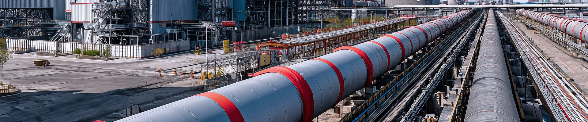
Standard rigid frames sometimes fail to handle highly aggressive operational forces. We frequently introduce suspended dynamic hardware as a strategic engineering choice. A Conveyor belt Garland Troughing Idler replaces the traditional fixed steel bracket. It functions effectively as a suspended, multi-roll set linked flexibly by chains or metal lugs. This unique design allows independent vertical movement along the trough profile. We strategically deploy these flexible sets in high-stress impact zones. They quickly resolve structural bottlenecks where standard rigid frames suffer premature failure.
Dynamic Load Management
Heavy material impacts severely punish fixed conveyor infrastructure. We see massive destructive force spikes whenever large lumps drop from chutes. Garland idlers physically shift and flex under these active vertical loads. They proactively absorb the sudden shock of heavy ROM rock. A standard rigid 4-foot spacing setup forces this impact energy entirely onto the rubber belt cover. It also transmits catastrophic shock directly into the rigid roller bearings. Suspended hardware dissipates this kinetic energy safely. The flexing motion significantly protects both the expensive conveyor belt and the internal roller mechanisms.
Mitigating Alignment-Induced Sag
Accurate load centering directly influences uniform sag behavior across the belt. Poorly centered material drops on rigid idlers cause severe uneven sag. One side of the belt droops further, creating aggressive tracking issues. Garland idlers naturally self-center the active load. The suspended chains sway slightly to accommodate off-center material flows. They dynamically adjust their shape to keep the troughing profile perfectly consistent. This constant self-correction prevents the localized edge flattening which inevitably leads to side spillage.
Shortlisting Criteria
Engineers evaluating replacement idlers must look far beyond basic static CEMA classes like C, D, or E. You need specific dynamic engineering metrics to guarantee long-term field performance.
Calculated Idler Load (CIL): Always verify the true expected vertical load against the manufacturer's stated rating.
Dynamic Load Factors: Apply a multiplier between 1.5 and 1.8 for demanding long overland applications.
L10 Bearing Life: Demand certified manufacturer guarantees for rotational lifespan under full load conditions.
Seal Integrity: Ensure robust multi-labyrinth seals protect internal bearings from highly abrasive dust.
Implementation Realities: Adjusting the 4-Foot Rule for Complex Zones
Convex Curves (Vertical Curves)
Unique belt path geometry alters standard spacing rules completely. A 4-foot spacing remains entirely unacceptable on sharp convex vertical curves. The belt pulls tightly against the steel rolls as it crests the curve radius. We follow a strict operational rule of thumb here. Spacing on convex curves must be reduced to exactly half the standard spacing. This drops the allowed span to precisely 2 feet. Closer supports prevent excessive edge tension build-up. They also stop severe idler junction fatigue from destroying the rubber carcass prematurely.
Graduated Idler Spacing
Operating tension varies wildly along the total length of any conveyor. We use graduated idler spacing strategies to match these varying physical realities. You deploy much closer spacing near the tail pulley. Tension measures lowest here, meaning sag risk measures highest. As the loaded belt approaches the head pulley, tension naturally increases. You can then safely expand the hardware supports back out to the full 4-foot spacing. This graduated design approach optimizes your overall hardware investment while fully preventing material spillage.
Transition Points
The belt shape changes drastically from completely flat to fully troughed at terminal ends. These critical transition zones require careful engineering oversight. We emphasize the clear need for adjustable transition idlers here. The belt moves from a flat tail pulley directly into a fully troughed 4-foot spacing section. Fixed rigid frames create extreme localized stretching along the outer belt edges. Adjustable transition sets allow a much safer, gradual forming process. This stepped approach minimizes destructive mechanical stress on the outer rubber margins.
Conveyor Zone
Recommended Spacing Rule
Primary Engineering Objective
Standard Horizontal Run
4 feet (48 inches)
Maintain max 2% sag; balance tension & component wear
Convex Curves
2 feet (24 inches)
Prevent massive edge tension and internal junction fatigue
Tail Pulley Exit
Graduated (e.g., 2 ft to 3 ft)
Compensate for inherently low baseline tension levels
High-Impact Load Zones
1.5 feet to 2 feet
Absorb lump kinetic energy; protect belt cover
Conclusion
Maintain absolute discipline regarding limits; allowing sag to surpass 0.96 inches at a 4-foot spacing guarantees accelerated component degradation.
Audit your slack side tension frequently to verify the drive system actively supports the necessary sag baseline under full production loads.
Monitor your cross-sectional fill percentages strictly; keeping capacities below 70% provides a crucial safety margin against edge spillage.
Upgrade vulnerable system bottlenecks by replacing rigid steel frames with suspended garland idler systems to dramatically improve shock absorption and load centering.
FAQ
Q: Does a heavier belt reduce sag on a 4-foot idler spacing?
A: No. A heavier belt actually increases the total mass (Wb) between the idlers. The increased gravitational pull on the heavier rubber requires significantly more applied tension to maintain the exact same 2% sag limit. Relying on belt weight to fix structural sag problems ultimately damages your pulleys.
Q: How does material lump size affect idler spacing decisions?
A: Large lumps create extremely high impact forces during transit. If belt sag exceeds 1%, the heavy lump effectively crashes into the next idler frame. This harsh mechanical impact drastically reduces the L10 bearing life of the steel roller. Processing heavy rock mandates much closer hardware spacing.
Q: Can I use identical idler ratings for both carrying and return sides?
A: While physically possible, it is commercially inefficient. Return idlers carry only the empty belt weight. They endure much lower continuous stress levels. You can typically use a lighter load rating or much wider spacing—often up to 10 feet—compared to the fully loaded 4-foot carrying side.